Microsoft ISA / TMG NLB mulicast unicast explained
- Angelo Schalley
- Jan, 15, 2012
- ISA/TMG, Networking, Windows-Microsoft
- No Comments
Unicast Mode
NLB can be configured to work in either unicast or multicast mode. These modes determine how the cluster assigns itself MAC addresses. The upstream router needs to send packets destined for the cluster based on the MAC address advertised by the cluster. The cluster MAC address needs to be the same for all virtual IP addresses because all packets destined for a virtual IP address must be delivered to all members of the NLB array.
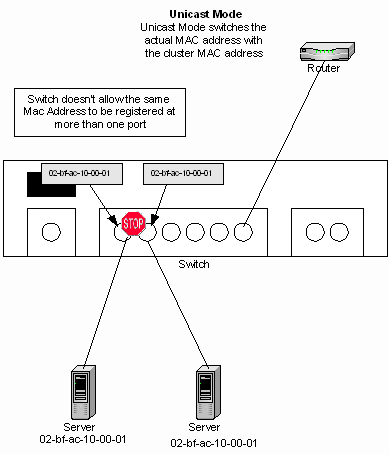
The NLB default setting is unicast mode. In unicast mode, NLB replaces the actual MAC address on each NLB adapter to a common NLB MAC address (as seen in the figure below). When all the NLB adapters have the same MAC address, all packets forwarded to that address are sent to all members of the NLB array. However, a problem with this configuration when the NLB array adapters are connected to the same switch. You can’t have two ports on the switch register the same MAC address.
NLB solves this problem by masking the cluster MAC address. The switch learns MAC addresses associated with its ports by looking at the source MAC address in the Ethernet frame header. NLB will create a bogus MAC address and assign that bogus MAC address to each adapter in the NLB array. NLB will assign each NLB adapter a different bogus MAC address based on the host ID of the array member and this address will appear in the Ethernet frame header.
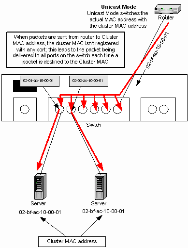
For example, in the figure below the NLB array MAC address is 02-bf-ac-10-00-01. NLB in unicast mode will take the array MAC address and for each NLB array member adapter change the second octet so that it consists of the NLB member’s host ID. So in the example below, host ID number 1 has the bogus MAC address 02-01-ac-10-00-01, host ID number 2 has the bogus MAC address 02-02-ac-10-00-01, host ID number 3 has the bogus MAC address 02-03-ac-10-00-01, and so on.
You might be wondering “if you register a unique MAC address on each switch port, how will the packets be delivered to all members of the array? Packets should still be sent to the individual switch ports based on the MAC address assigned to that port”. If you’re wondering how frames will be delivered to all members of the NLB array when each switch port connected to an NLB array member registers a different MAC address, then you’re asking the right questions.
In order to answer that question, you need to think about how the upstream router learns the MAC address of the destination server. The router doesn’t query switch ports, it uses an ARP broadcast. When the router sends an ARP request for the MAC address of the virtual IP address, the ARP header contains the actual NLB MAC address and not the bogus MAC address.
Look at the packet trace information below. Notice that the Ethernet frame reports the source MAC address in the ARP reply to be 0201AC100001. Notice that the second octet in the MAC address is 01; this is host ID number 1 in the array and this is a bogus unicast MAC address. Look at the ARP_RARP header information. The ARP_RARP header shows that source MAC address to be 02BFAC100001. This is the NLB array address that accepts packets for all virtual IP addresses bound to the array. The router uses the MAC address in the ARP header, not the Ethernet header. The switch uses the MAC address in the Ethernet header, not the ARP header. Pretty clever, eh?
ARP_RARP: ARP: Reply, Target IP: 172.16.0.4 Target Hdwr Addr: 005056404200
16 5.868438 0201AC100001 LOCAL ARP_RARP ARP: Reply, Target IP: 172.16.0.4 Target Hdwr Addr: 005056404200
Frame: Base frame properties
Frame: Time of capture = 1/28/2003 13:36:54.52
Frame: Time delta from previous physical frame: 20029 microseconds
Frame: Frame number: 16
Frame: Total frame length: 60 bytes
Frame: Capture frame length: 60 bytes
Frame: Frame data: Number of data bytes remaining = 60 (0x003C)
ETHERNET: ETYPE = 0x0806 : Protocol = ARP: Address Resolution Protocol
ETHERNET: Destination address : 005056404200
ETHERNET: …….0 = Individual address
ETHERNET: ……0. = Universally administered address
ETHERNET: Source address : 0201AC100001
ETHERNET: …….0 = No routing information present
ETHERNET: ……1. = Locally administered address
ETHERNET: Frame Length : 60 (0x003C)
ETHERNET: Ethernet Type : 0x0806 (ARP: Address Resolution Protocol)
ETHERNET: Ethernet Data: Number of data bytes remaining = 46 (0x002E)
ARP_RARP: ARP: Reply, Target IP: 172.16.0.4 Target Hdwr Addr: 005056404200
ARP_RARP: Hardware Type = Ethernet (10Mb)
ARP_RARP: Protocol Type = 2048 (0x800)
ARP_RARP: Hardware Address Length = 6 (0x6)
ARP_RARP: Protocol Address Length = 4 (0x4)
ARP_RARP: Opcode = Reply
ARP_RARP: Sender’s Hardware Address = 02BFAC100001
ARP_RARP: Sender’s Protocol Address = 172.16.0.1
ARP_RARP: Target’s Hardware Address = 005056404200
ARP_RARP: Target’s Protocol Address = 172.16.0.4
ARP_RARP: Frame Padding
While this is a clever solution to the problem of assigning the same MAC address to multiple ports on the same switch, it introduces another problem. When the router forwards frames to the NLB array MAC address, no port on the switch has the NLB array MAC address registered and therefore the frame is delivered to all switch ports. This introduces “switch flooding”. Switch flooding typically isn’t a problem for incoming messages because overwhelming majority of traffic is outbound, not inbound. But if you have a significant amount of inbound traffic and also have other servers on the same switch, switch flooding can present a big problem.
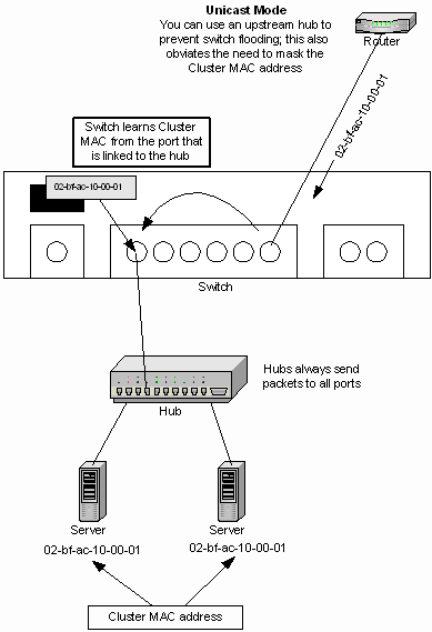
A solution to switch flooding is to put a simple hub in front of the NLB array members and then uplink the hub to a switch port. You don’t even need to mask the NLB array MAC address with this configuration because the single switch port connected to the hub learns the NLB array MAC address. This avoids the problem of two switch ports registering the MAC same address. When the router sends packets to the NLB array MAC address, the packets go directly to the switch port connected to the hub the NLB array members are connected to.
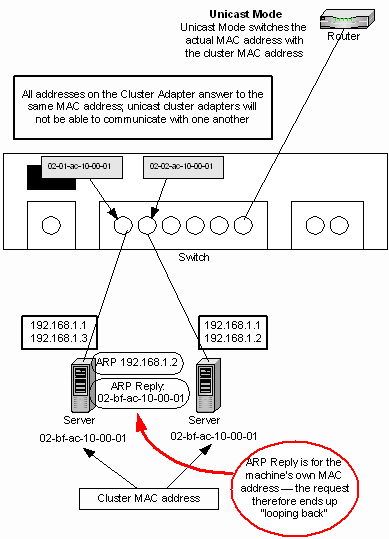
There’s one more problem we have to deal with when running the NLB array in unicast mode. That problem is that the NLB adapter will not be able to communicate with one another via their dedicated IP addresses. A dedicated IP address is an address that a single array member will answer on. The dedicated IP address is separate and distinct from all other IP addresses used in the array.
For example, in the figure below the servers have a virtual IP address of 192.168.1.1. One server has a dedicated IP address of 192.168.1.2 and another has a dedicated IP address of 192.168.1.3. What happens when one NLB array member needs to communicate with another NLB array member using their dedicated IP addresses? You might think “no problem, the dedicated IP addresses can use the bogus MAC address used when you mask that NLB array MAC address”. The problem is that the two NLB adapters won’t be able to communicate with one another.
You can see what happens in the figure below. ISA1 at 192.168.1.3 sends and ARP request for ISA2 at 192.168.1.2. ISA2 answers with the NLB array MAC address. The problem is that this is the same address used by ISA1! This “loopback” phenomenon prevents the NLB adapters on each array member from communicating with one another.
The recommended solution is to install a second NIC on the same network ID and assign a dedicated IP address to that adapter. You would do this if you needed to back up data from one server to another, such as replicating Web site data. However, adding a second network adapter on the same network ID is not a viable solution for ISA Sever arrays and fortunately its not required.
Note:
Unicast mode allows you to assign a dedicated IP address to each member in the array. However, all frames are always delivered to all members of the array. Frames are passed up the TCP/IP stack and are accepted or dropped based on the destination IP address in the communication and the dedicated IP address. If the dedicated IP address and the IP address in the packet don’t match and the destination address is not the shared VIP, then the stack drops the packet. The disadvantage of unicast mode and the dedicated IP addresses is that incoming traffic to the dedicated IP address is delivered to all members of the array.
Multicast Mode
The other NLB mode is multicast mode. Microsoft would prefer to set the default mode to multicast, but there are problems because certain Cisco devices don’t allow multicast MAC addresses to be associated with a unicast IP address and the Cisco device will not insert a multicast MAC address its ARP table if its associated with a unicast IP address.
Before we get more into the subject of multicast mode, we should go over concept of the multicast MAC address. Multicast MAC addresses allow multiple computers to listen on the same MAC address. All the machines listening on the same multicast MAC address are referred to as a “multicast group”. A single NIC can listen on both a unicast MAC address and a multicast MAC address in the same way that it can listen on a unicast IP address (such as 192.168.1.1) and a multicast IP address (such as 224.0.1.24). Frames sent to the multicast MAC address are accepted by the adapters listening on that multicast address and frames directed to a unicast MAC address are accepted by the single host that owns the particular unicast address.
This multicast MAC address allows you to “spray” frames to all switch ports, since switch ports never automatically register multicast addresses. The frames are passed up the TCP/IP stack to the higher level protocols for further processing. Even though the NIC driver accepts frames sent to the multicast MAC address, they can still be dropped by the higher level protocol, such as when port rules determine that a particular host would not handle requests for the destination TCP or UDP port in the packet.
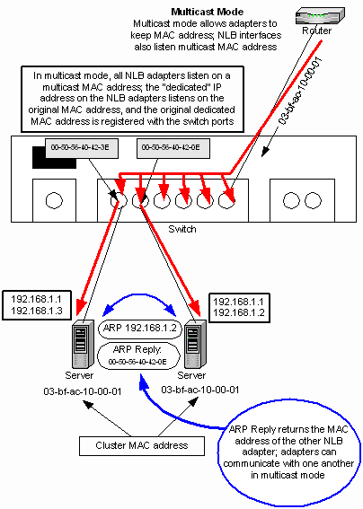
When you use NLB in multicast mode, the NLB adapters retain their original MAC addresses and this address is used to communicate with individual members in the array via the dedicated IP address on each array member. Since the dedicated IP address bound to the NLB adapter is associated with a unique MAC address, the NLB adapters are able to communicate with one another. When one adapter sends an ARP request for the dedicated IP address of another adapter in the array, the adapter will respond to the ARP with its is own actual MAC address, not the NLB MAC address.
Network switches vary in how they handle frames directed to multicast MAC addresses. Simple SOHO switches pass the frames to all switch ports in the same way that happens with the switch flooding you see with unicast mode, as you see in the figure below. More sophisticated switches can be configured to recognize the multicast group and limit multicast frame delivery to the ports that have members of that multicast group.
Quick Tip: You can tell a multicast MAC address from a unicast MAC address by looking at the high order octet in the MAC address. If the low order bit in the high order octet in the MAC address is 1, then the address is a multicast MAC address. If the low order bit in the higher order octet in the MAC address is 0, then the address is a unicast MAC address.
The figure below shows an ARP Reply from a multicast NLB array member.
2 231.773273 LOCAL 00505640423E ARP_RARP ARP: Reply, Target IP: 172.16.0.2 Target Hdwr Addr: 00505640423E
Frame: Base frame properties
Frame: Time of capture = 1/31/2003 13:50:16.679
Frame: Time delta from previous physical frame: 0 microseconds
Frame: Frame number: 2
Frame: Total frame length: 42 bytes
Frame: Capture frame length: 42 bytes
Frame: Frame data: Number of data bytes remaining = 42 (0x002A)
ETHERNET: ETYPE = 0x0806 : Protocol = ARP: Address Resolution Protocol
ETHERNET: Destination address : 00505640423E
ETHERNET: …….0 = Individual address
ETHERNET: ……0. = Universally administered address
ETHERNET: Source address : 00505640420E
ETHERNET: …….0 = No routing information present
ETHERNET: ……0. = Universally administered address
ETHERNET: Frame Length : 42 (0x002A)
ETHERNET: Ethernet Type : 0x0806 (ARP: Address Resolution Protocol)
ETHERNET: Ethernet Data: Number of data bytes remaining = 28 (0x001C)
ARP_RARP: ARP: Reply, Target IP: 172.16.0.2 Target Hdwr Addr: 00505640423E
ARP_RARP: Hardware Type = Ethernet (10Mb)
ARP_RARP: Protocol Type = 2048 (0x800)
ARP_RARP: Hardware Address Length = 6 (0x6)
ARP_RARP: Protocol Address Length = 4 (0x4)
ARP_RARP: Opcode = Reply
ARP_RARP: Sender’s Hardware Address = 00505640420E
ARP_RARP: Sender’s Protocol Address = 172.16.0.3
ARP_RARP: Target’s Hardware Address = 00505640423E
ARP_RARP: Target’s Protocol Address = 172.16.0.2
